magnetLAB

IASA

Text Box: | Home | Magnetic Field Mapping | News | Downloads | About Us | Contact Us |

Magnetic Field Mapping Project in IASA

© Copyright 2004~2005, IASA—magnetLAB group. Institute of Accelerating Systems & Applications,

P.O. Box 17214 GR—10024, Athens GREECE.

Google
WWW http://www.iasa.gr/magnetLAB/magnetLAB.html

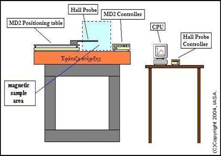
The magnetic field mapping device:


   The main aim of the magnetLAB group was to create a device which could scan a 2D accurately defined area. The whole process should be totally automated, so that after pre-scanning software adjustments no further external interferences should be needed. The reason for this is that accurate field measurements demand long time periods, which make it a boring and tiring process for the scientist who studies a magnetic system.
The main parts of the mapping device are shown in figure 1.

   The device has the ability to measure fields in the areas of 0.3, 0.6, 1.2 and 3 Tesla. The error in measuring is 0.000005 Tesla and the field sensor (Hall Probe) takes 10 measurements per second. The relevant error for fields suitable for 5 MeV electron beams is 0.67/10000 and the half for the 10 MeV beams which will be developed in the future.
     The resolution in both axis is 1 twip which equals to 0.125 mm.
 

Figure 1:

IASA Magnetic Field Mapper

   The twip unit has been introduced in order to refer to one full step of the stepping motors that are used to move the device's field sensor in a specific point of the 2D area that is mapped.
      As already said the device is fully controlled by a computer and when the mapping process starts no external interference  is needed or aloud. The scientist can stop or pause the process. The software which has been specifically developed  for the mapper has been sliced into two parts:


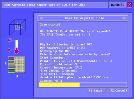
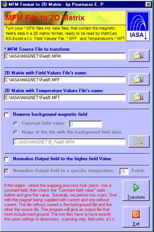
1. The data acquisition software (magnet1.exe)

2. The magnetic field reconstruction software (tran1.exe)
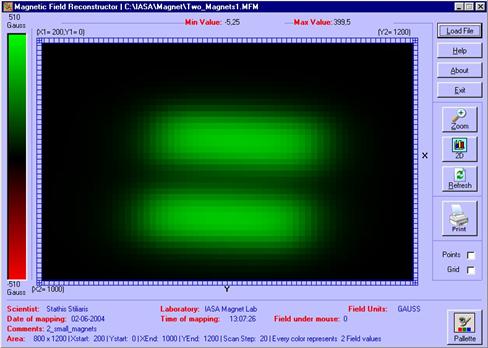
Figure 2:
"The scanning process"

   The 1st part has been written for DOS in order to make use of the real time characteristic of this operating system. Although, it can run under Windows, too. It also makes use of the GP-IB scientific instruments communication technology. The 2nd part is written for Windows, because this operating system has a plethora of visualization tools.
   The magnetic field's data are stored in a ASCII format following a specific storing protocol, which has the recognizable extension MFM. The reconstruction software transforms the *.MFM files into 2D matrixes that can be visualized by Excel, MathCAD e.t.c. The MFM files contain data for magnetic field and temperature, that are extracted by Tran1.exe into *.MFF and *.MFT output ASCII data files.
     A limited visualization software has also been developed. It has low diversifying abilities, but it can produce quick diagrams by reading un-transformed MFM files.


Figure 4:
"The reconstruction software, which prepares data to be
 visualized by leading packets such as MathCAD ®

Figure 3:
"The magnetic field of two natural magnets"

Magnetic Field Samples